In HVAC systems, plate heat exchangers handle core functions such as heat transfer, cooling distribution, and system isolation. A well-designed PHE can reduce the energy consumption of the entire system by 5–15%. This article outlines four typical HVAC application scenarios.
I. Overview of the Four Application Scenarios
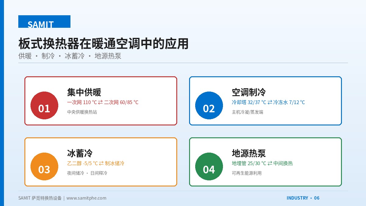
① Central Heating Substation
Isolates and exchanges heat between the primary network (heat source 110–130 °C) and the secondary network (end user 50–85 °C), protecting primary water quality and regulating secondary temperature.
- Typical K: 4000–5000 W/(m²·K)
- Medium: softened hot water
- Pressure drop: ≤ 50 kPa
② Chiller Main Unit
Auxiliary heat exchange for the condenser and evaporator of water chillers, or isolation between the cooling tower and chilled-water system. Can also recover condenser waste heat.
- Typical K: 3500–4500 W/(m²·K)
- Medium: water / R134a / ethylene glycol
- Pressure drop: ≤ 40 kPa
③ Ice Storage System
Ice is produced at night for cold storage and melted during the day for cooling. The PHE serves as the heat-transfer interface between the ice tank and chilled water, handling glycol–water heat exchange.
- Typical K: 2500–3500 W/(m²·K)
- Medium: 25% ethylene glycol aqueous solution
- Pressure drop: ≤ 60 kPa
④ Ground-Source Heat Pump System
Exchanges heat between the buried-pipe circulating water and the unit's intermediate water, isolating contaminants on the buried-pipe side to ensure stable unit operation.
- Typical K: 4000–5000 W/(m²·K)
- Medium: circulating water / ethylene glycol
- Temperature difference: 5–8 °C
II. Typical Design of a Heating Substation
The central heating substation is the most classic PHE application in HVAC. The figure below shows a typical indirectly connected substation flow diagram:
III. Energy-Saving Benefits of Ice Storage Systems
Ice storage principle: At night, off-peak electricity is used for refrigeration; 25% ethylene glycol solution is cooled to −5 °C and freezes water in the storage tank. During daytime peak hours, glycol flows through the tank to melt the ice, then enters the PHE to exchange heat with chilled water and supply cooling to end users.
Economic analysis (10,000 m² commercial building example):
- Peak cooling load: 1000 kW, 10 h daily operation
- Night ice-making: 8 h (off-peak rate RMB 0.30/kWh)
- Daytime ice-melting: 6 h (peak rate RMB 1.20/kWh)
- Peak-shaving ratio: ~40%, annual electricity savings RMB 150,000–200,000
- PHE investment: ~RMB 80,000 (including glycol-dedicated plates)
- Payback period: 6–8 months
IV. HVAC Selection Essentials
| Application | Plate Material | Gasket | Key Parameters |
|---|---|---|---|
| Heating (hot water) | 304 / 316L | EPDM | K ≥ 4500, pressure drop ≤ 40 kPa |
| Chilled water | 304 | EPDM | K ≥ 4000, temperature difference 5 °C |
| Glycol system | 316L | EPDM | K reduced by 25%, ΔP raised by 30% |
| Cooling tower side | 316L | EPDM | Fouling factor 0.85, open system |
| Closed-loop | 304 | EPDM | K at upper limit, service life 15+ years |
V. Summary
HVAC is the largest application field for plate heat exchangers. Mastering the design conditions and selection essentials for the four scenarios—heating, refrigeration, ice storage, and ground-source heat pumps—will let you handle most HVAC projects. Key points: reduce K for glycol systems, account for fouling margin in open systems, and pay attention to climate-compensation control in heating applications.