Plate heat exchanger selection directly determines whether the equipment can operate stably and long-term under design conditions, yet many field engineers' selection practice remains at the level of "ask for flow rate, look up the catalog." This article provides a reusable selection workflow from three perspectives: parameter collection, thermal calculation, and case validation.
I. Six Fundamental Selection Parameters
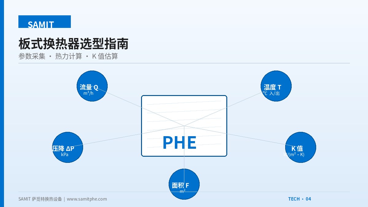
Six core parameters must be collected before selection. Missing or inaccurate parameters will cause selection deviation:
① Flow Rate Q
Volumetric flow rate (m³/h) or mass flow rate (t/h) on both hot and cold sides. Note the difference between peak and average flow rates; select based on the design flow rate.
② Temperature T₁/T₂
Inlet and outlet temperatures on both hot and cold sides. All four temperature points must be clearly defined; they determine the heat load Q=kW and the Logarithmic Mean Temperature Difference (LMTD).
③ Medium Properties
Density, specific heat, viscosity, thermal conductivity. The same model with different media (water vs oil vs ethylene glycol) can have K value differences of up to 50%.
④ Allowable Pressure Drop ΔP
Typically ≤ 50 kPa on the process side, ≤ 30 kPa on the circulating water side. The stricter the pressure drop, the larger the required heat transfer area.
⑤ Working Pressure / Temperature
Determines plate thickness, gasket material, and frame rating. Above 1.6 MPa or 150 ℃, special design is usually required.
⑥ Special Requirements
Solid particles present (requires wide channel), sanitary grade (food/pharmaceutical), highly corrosive (high-alloy), footprint constraints, etc.
II. Five-Step Thermal Calculation Workflow
The core calculation workflow from parameters to model is as follows:
III. Case Study: 4000 kW Heating Station Selection
A district heating station exchanges primary network high-temperature water with secondary network heating water. Design conditions are as follows:
| Parameter | High-Temperature Side (Primary Network) | Low-Temperature Side (Secondary Network) |
|---|---|---|
| Medium | Softened hot water | Softened hot water |
| Inlet temperature | 110 ℃ | 50 ℃ |
| Outlet temperature | 75 ℃ | 85 ℃ |
| Flow rate | 110 m³/h | 105 m³/h |
| Allowable pressure drop | 40 kPa | 50 kPa |
Step-by-step calculation per the workflow above:
- Heat load Q: Q = ρ·c·q·ΔT = 1000 × 4.18 × (105/3600) × (85-50) ≈ 4265 kW (4000 kW taken with design margin)
- LMTD: ΔT₁ = 110-85 = 25, ΔT₂ = 75-50 = 25, LMTD = 25 ℃ (when counter-flow temperature differences are equal, it equals the arithmetic mean)
- Estimate K: For water-to-water plate heat exchangers, take empirical value 5000 W/(m²·K)
- Area F: F = Q/(K·LMTD) = 4×10⁶/(5000×25) = 32 m², take 1.15 margin = 36.8 m²
- Selection: Choose SAMIT BR0.5 plate model (0.5 m² per plate), 74 plates in total, actual area 37 m²
Verification: Pressure drop calculation ΔP = 38 kPa (hot side) / 45 kPa (cold side), both below the allowable values; the selection is qualified. If the pressure drop exceeds the limit, switch to a shallow-corrugation plate type or increase the number of plates.
IV. Common Selection Pitfalls
① Looking only at flow rate, ignoring temperature difference
At the same flow rate, temperature differences of 5 ℃ vs 30 ℃ require 5–6 times the area. Selecting purely by flow rate is almost certainly wrong.
② Taking the upper end of catalog K values
The K range given in catalogs is a range. Water-to-water PHE values of 4000–7000 are for clean conditions; for fouling conditions, take 60% of the value.
③ Ignoring medium properties
The K value of the same model handling oils is only 800 W/(m²·K), 6 times lower than for water. Switching media requires recalculation.
④ Leaving no margin
An area margin of 10–20% is essential; fouling, flow fluctuation, and temperature drift all need to be absorbed by the margin.
⑤ Ignoring pressure drop constraints
A plate heat exchanger with excessive pressure drop will overload the circulating pump and significantly increase long-term operating energy consumption.
⑥ Ignoring fouling margin
Open circulating water systems scale quickly; an additional fouling factor of 0.85–0.9 should be applied.
V. Summary
Selection is an iterative process of "parameters → calculation → verification → adjustment." Mastering 6-parameter collection + 5-step calculation workflow combined with empirical K values for typical conditions allows you to independently complete 80% of routine selections. For complex conditions (phase change, highly corrosive, high pressure), it is recommended to have the manufacturer's engineers verify using specialized software.