A plate heat exchanger may look simple—two end plates clamping a stack of corrugated plates—but achieving high efficiency, reliability, and long service life requires careful design of each component. This article breaks down the eight core components and explains PHE model number coding.
I. Eight Core Components
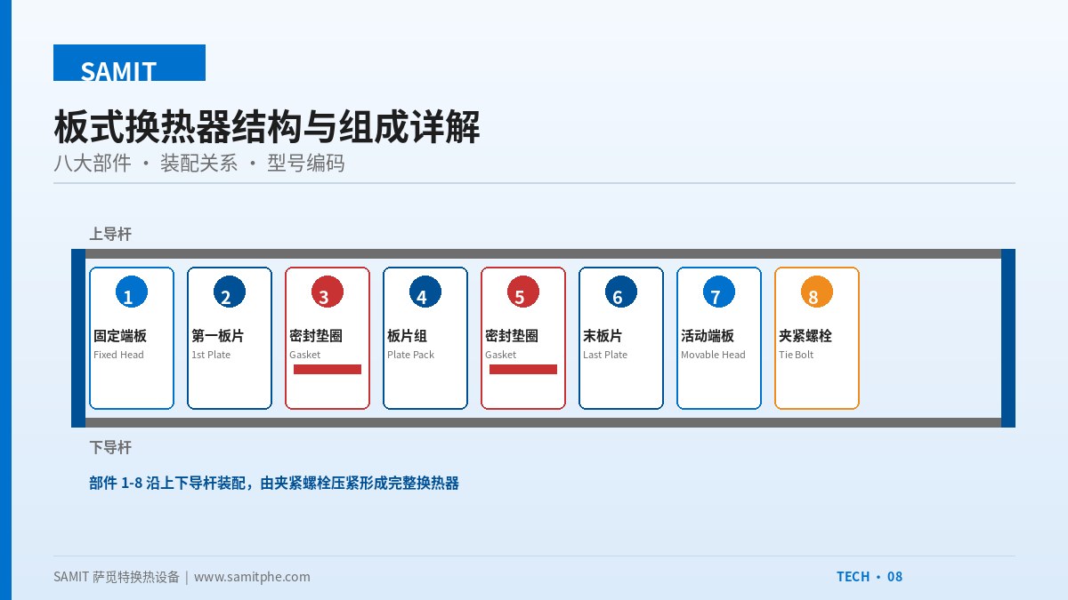
① Fixed Frame Plate
One end is fixed to the frame and carries the inlet/outlet nozzles. It has four corner ports (inlets and outlets for hot and cold media) for connection to external piping.
② Movable Pressure Plate
Slides along the upper guide bar for plate assembly and disassembly. When clamped, it works with the fixed frame plate to compress the plate pack.
③ Plate Pack
The heat-transfer core. Each plate ranges from 0.03–2.5 m²; the corrugated pattern generates turbulence and enhances heat transfer. Hot and cold plates are arranged alternately.
④ Sealing Gaskets
Installed at plate corner ports and perimeters, providing "two seals + one leakage drain". Available in EPDM, NBR, Viton, silicone, and other materials.
⑤ Upper Guide Bar
Supports the plates and movable pressure plate to ensure assembly concentricity. Bears the clamping force.
⑥ Lower Guide Bar
Parallel to the upper guide bar; carries the weight of the plates and ensures horizontal positioning.
⑦ Tightening Bolts
Several large-diameter threaded rods distributed around the circumference. Rotating the nuts pushes the movable pressure plate to compress the plate pack and achieve sealing.
⑧ Columns and Base
Support the entire weight of the equipment. Equipped with leveling bolts to adjust equipment level and drain slope.
II. Assembly Exploded View
III. Plate Corrugation Types Compared
Plate corrugation is the core of heat-transfer enhancement. Different patterns suit different duties:
| Corrugation Type | Typical K | Pressure Drop | Applications |
|---|---|---|---|
| Chevron (V-shaped) | 5000–7000 | Higher | Water–water, low-viscosity liquids; most common |
| Horizontal straight corrugation | 3000–4500 | Lower | Oils, medium-viscosity media |
| Serrated | 4000–5500 | Medium | Media with small amounts of particles or fibers |
| Point protrusions | 3500–5000 | Low | High-viscosity, fouling-prone media |
| Long straight channel (wide channel) | 2500–4000 | Low | Fibrous media, pulp, sewage |
| Shallow corrugation (sanitary grade) | 4500–6000 | Medium | Food, pharmaceuticals (no dead corners) |
IV. Model Number Interpretation
Example model: SAMIT BR0.5-1.6/150-30A
Segment-by-segment breakdown:
- BR — Stainless-steel chevron-corrugated PHE (B = R indicates PHE, R = chevron corrugation)
- 0.5 — Single-plate heat-transfer area 0.5 m²
- 1.6 — Rated working pressure 1.6 MPa
- 150 — Rated working temperature 150 °C
- 30 — Nominal heat-transfer area 30 m²
- A — Frame type (A = suspended, B = double-support)
A more detailed model (including pass-coding) example:
MBR0.3-1.20/120-30A-(10×5)/(4×8+2×9)
The parentheses indicate the pass arrangement:
- (10×5): Hot medium — 10 passes, 5 channels per pass
- (4×8+2×9): Cold medium — 6 passes (4 passes × 8 channels + 2 passes × 9 channels)
The number of passes and channels together determine the flow velocity, pressure drop, and heat-transfer capacity within the PHE.
V. Summary
Mastering the functions and assembly relationships of the eight PHE components is the foundation for understanding equipment operation and troubleshooting. Reading model numbers lets you quickly judge equipment specifications during selection, procurement, and maintenance. Engineers are advised to review their on-site PHEs against this article—creating a complete "model + component" file—to build comprehensive equipment records.